100-001-D: Rugged PoE for Starlink (with smart fusing)
Overview
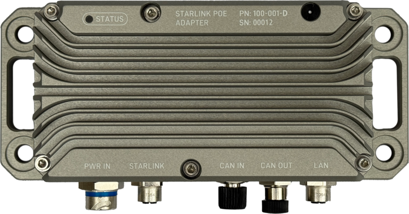
The Rugged PoE for Starlink is a military-grade power solution designed to enable Starlink connectivity in the most demanding environments. Built to MIL-STD-810 standards, this robust power converter eliminates inefficiencies in standard AC-to-DC conversion while providing remote monitoring and control capabilities through DroneCAN integration.
3D Model
Explore the Rugged PoE for Starlink in 3D. Rotate, zoom, and pan to examine all details.
View in AR
Scan with mobile device
CAD Compatible:
SolidWorks, Fusion 360, FreeCAD, OnShape
Controls: Left mouse to rotate • Scroll to zoom • Right mouse to pan
Installation Guide
- To ensure waterproofing, mate all cables or plug unused ports with protective caps (Male: TE 2823064-1 | Female: Phoenix 1560251).
- Improper termination of power or Starlink cables can destroy internal circuitry.
- Do not over-torque 1/4" mounting bolts and over-compress isolation washer.
- Up to 50 in-lbs is acceptable if no rubber isolator is used.
- Use of self-locking fasteners recommended for mounting.
- Apply Permatex 81343 Anti-Seize to stainless steel mounting bolts and lock nuts to prevent galling during installation and future removal.
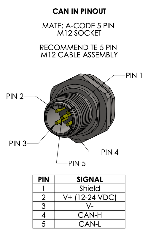
- CAN termination can be done digitally or physically. The digitally controlled termination resistor is configured via the DroneCAN parameter CAN_TERM (set to 1 for enable 0 to disable). The digitally controlled termination resistor is on by default. Externally configured CAN termination resistors can also be added where appropriate to terminate the lines for a total bus impedance of 60 ohms.
- Apply light amount of Loctite LB 8423 (or equivalent) dielectric grease to connector mating interfaces before connection. Wipe away excess after mating cables.
Cable Selection

Standard Starlink
Cable Part Number: 100-080-A
Wiring Notes:
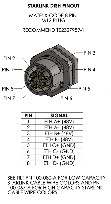
The Standard Starlink dish cable follows standard T568B color nomenclature with typical gauge wire suitable for the dish's power requirements.
Field termination requires cutting and splicing the original Starlink cable to connect to the M12 industrial connector following the pinout diagram.

Flat High Performance Dish
Cable Part Number: 100-067-A
⚠️ Warning: Non-Standard Wiring
The Flat High Performance dish cable uses NON-STANDARD color coding that does NOT follow T568B conventions. Additionally, it uses thicker gauge wire to handle the increased power demands.
Critical: Carefully follow the pinout diagram as wire colors WILL NOT match standard Ethernet conventions. Improper termination can damage equipment.
Power Management / Design
Input Power Requirements
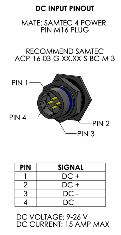
The Rugged PoE accepts a wide range of DC input voltages, making it compatible with various power sources:
- 12V Systems - Standard automotive/marine batteries
- 24V Systems - Military vehicles, commercial trucks
- 28V Systems - Aircraft power systems
- 36V Systems - Industrial equipment
Critical for 12V Systems
When operating at 12V, strict adherence to IEC 61000-2-2 voltage ripple standards (≤3%) is absolutely critical. At maximum 18A draw, even small voltage drops can cause system instability. A mere 0.36V drop (3% of 12V) can trigger intermittent failures, network routing issues, and unexpected disconnections. Higher voltage systems (24V-36V) have more tolerance for voltage variations, but 12V systems require meticulous attention to wire gauge selection and connection quality to ensure reliable operation.
Electrical Connections
Critical Wiring Requirements
Proper wire gauge selection is essential for safe and reliable operation. Undersized wiring can cause excessive voltage drop, system instability, and potential fire hazards. Target voltage ripple should be ≤3% per IEC 61000-2-2 and IEEE 519 standards. For 18A at 12V, this means maintaining less than 0.36V drop across the entire wire run. Always size conductors to maintain voltage drop within acceptable limits for your specific installation length and current requirements.
Starlink Network Recovery Issue
If input power becomes insufficient (e.g., voltage drop during engine start), Starlink will stop routing TCP and UDP traffic to connected devices. This network lockup condition will persist even after power is restored and requires a full power cycle to recover. Ensure your power system can maintain adequate voltage during all operating conditions to prevent network disruptions.
DC Input Cable Sizing Calculator
System Configuration
Installation Parameters
Compliance Status
LED Indicators

Red (Solid)
System initializing

Red (Flashing 5Hz)
Fault Detected

White
System On

Green
POE enabled & operating
Fault Indication
Red (Flashing 5Hz) - Fault condition detected (voltage, current, or temperature limit exceeded)
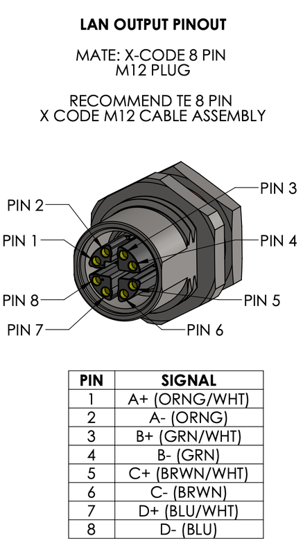
Pinouts

Troubleshooting
Common Issues and Solutions
| Issue | Possible Cause | Solution | Recovery Method | LED indication |
|---|---|---|---|---|
| Output over-voltage | Output exceeds TILT_MAX_VOLTS parameter | Check wiring and load conditions | Power cycle required | Flashing Red (5hz) |
| Output under-voltage | Output below TILT_MIN_VOLTS parameter | Check input power and wiring gauge | Power cycle required | Flashing Red (5hz) |
| Output over-current | Current exceeds TILT_MAX_CURR parameter | Reduce load or check for shorts | Power cycle required | Flashing Red (5hz) |
| Over-temperature fault | Temperature exceeds TILT_MAX_TEMP parameter | Improve ventilation/cooling | Auto-recovery* | Flashing Red (5hz) |
| Starlink not detected | Poor connection or power issue | Check cable connections and input voltage | Power cycle may be required | |
| Network traffic not routing | Power interruption occurred | Check cable connections and input voltage ripple <3% | Correct source power issues | |
| CAN communication failure | Incorrect termination impedance | Measure can impedance with vehicle powered off. | Insure bus impedance is 60 ohms |
Temperature Auto-Recovery
The over-temperature fault has a 10°C hysteresis for automatic recovery. When the device temperature exceeds the TILT_MAX_TEMP parameter, POE output is disabled. Once the temperature drops to (TILT_MAX_TEMP - 10°C), the POE output automatically re-enables without requiring a power cycle. For example, if TILT_MAX_TEMP is set to 85°C, the fault triggers at 85°C and auto-recovers at 75°C.
Fault Protection Parameters
The Smart Fusing model monitors these configurable parameters in real-time:
| Parameter | Default Value | Typical Range | Description |
|---|---|---|---|
| TILT_MIN_VOLTS | 44.0V | 41.0 - 47.0V | Minimum output voltage before fault |
| TILT_MAX_VOLTS | 51.0V | 49.0 - 51.0V | Maximum output voltage before fault |
| TILT_MAX_CURR | 5.25A | 4.0A - 5.5A | Maximum output current before fault |
| TILT_MAX_TEMP | 100 °C | 80 °C - 100 °C | Maximum temperature before fault |
Critical Fault Behavior
All electrical faults (voltage and current) require a full power cycle to reset. The system will not automatically recover from these conditions even if the fault condition clears. This is a safety feature to prevent damage from intermittent fault conditions.
Fault Detection Logic Flow
flowchart TD
    Start([POE System Running]) --> Monitor{Monitor Output<br/>Parameters}

    Monitor --> VoltCheck{Output Voltage<br/>Check}
    Monitor --> CurrCheck{Output Current<br/>Check}
    Monitor --> TempCheck{Temperature<br/>Check}

    VoltCheck -->|"V > TILT_MAX_VOLTS"| VoltFault[Over-Voltage Fault]
    VoltCheck -->|"V < TILT_MIN_VOLTS"| VoltFault2[Under-Voltage Fault]
    VoltCheck -->|Normal| Continue1[Continue Operation]

    CurrCheck -->|"I > TILT_MAX_CURR"| CurrFault[Over-Current Fault]
    CurrCheck -->|Normal| Continue2[Continue Operation]

    TempCheck -->|"T > TILT_MAX_TEMP"| TempFault[Over-Temperature Fault]
    TempCheck -->|Normal| Continue3[Continue Operation]

    VoltFault --> DisablePOE[Disable POE Output]
    VoltFault2 --> DisablePOE
    CurrFault --> DisablePOE
    TempFault --> DisablePOE

    DisablePOE --> FlashRed[Flash Red LED @ 5Hz]

    FlashRed --> FaultType{Fault Type?}

    FaultType -->|Voltage/Current| RequirePowerCycle[Require Power Cycle<br/>to Reset]
    FaultType -->|Temperature| WaitCool{Temperature<br/>< TILT_MAX_TEMP - 10°C?}

    WaitCool -->|No| WaitCool
    WaitCool -->|Yes| AutoRecover[Auto-Recovery:<br/>Re-enable POE]

    RequirePowerCycle --> PowerCycled{Power<br/>Cycled?}
    PowerCycled -->|Yes| Start
    PowerCycled -->|No| RequirePowerCycle

    AutoRecover --> Start

    Continue1 --> Monitor
    Continue2 --> Monitor
    Continue3 --> Monitor

    style VoltFault fill:#ff6b6b
    style VoltFault2 fill:#ff6b6b
    style CurrFault fill:#ff6b6b
    style TempFault fill:#ffa94d
    style DisablePOE fill:#ff6b6b
    style FlashRed fill:#ff6b6b
    style AutoRecover fill:#51cf66
    style PowerCycled fill:#51cf66
Cable Assemblies
Compatible Cables by Dish Type
Select the appropriate cable assembly for your specific Starlink dish model:
| Starlink Dish Type | Required Cable | Part Number | Description |
|---|---|---|---|
| Standard Starlink | Low Capacity | 100-080-A | Standard gauge conductors for normal power requirements |
| Flat High Performance | High Capacity | 100-067-A | Heavy gauge conductors for increased power demands |
Cable Selection
The High Performance dish requires the High Capacity cable due to its increased power consumption. Using the wrong cable type may result in system instability or failure to operate.
Safety Features
The Rugged PoE includes comprehensive protection systems to ensure reliable operation and prevent damage:
Automatic Protection
- Over-voltage Protection - Automatically disables output if output voltage exceeds safe limits
- Over-current Protection - Prevents damage when output current exceeds safe limits
- Thermal Protection - Shuts down output if temperature exceeds safe operating range
- Under-voltage Protection - Disables output when output voltage drops below minimum threshold
Real-time Monitoring
The Smart Fusing model continuously monitors: - Output voltage and current - Internal temperature - Output power status - Fault conditions
All parameters are broadcast via DroneCAN for remote monitoring and logging.
DroneCAN API Documentation
For detailed information on DroneCAN integration, message definitions, and configuration examples, see the DroneCAN API Documentation.
Configuration Parameters
Smart Fusing Model Only
Parameter configuration is available only on the Smart Fusing variant via DroneCAN
Configurable Parameters
| Parameter | Description | Default Value | Range |
|---|---|---|---|
| TILT_CAN_RATE_MS | POE telemetry broadcast rate (milliseconds) | 500ms (2Hz) | 100-5000ms |
| Max Voltage | Maximum input voltage before shutdown | 36V | 12-50V |
| Min Voltage | Minimum input voltage for operation | 12V | 10-36V |
| Max Current | Maximum current draw before protection | 18A | 1-25A |
| Max Temperature | Maximum operating temperature | 85°C | 50-100°C |
| Enable POE | Master enable/disable control | Enabled | On/Off |
Parameter Adjustment
Parameters can be adjusted via DroneCAN configuration tools to match specific installation requirements:
- Connect to the device using a DroneCAN interface
- Use configuration software to read current parameters
- Adjust thresholds as needed for your application
- Test system operation with new parameters
Safety Notice
Only adjust parameters within manufacturer specifications. Incorrect settings may damage equipment or create safety hazards.
Support Resources
- Technical Support: support@tiltautonomy.com
- Product Updates: Check this page for latest firmware and documentation
- Warranty: 1-year limited warranty against manufacturing defects (excludes damage from improper installation, misuse, or operation outside specifications)
Last updated: February 17, 2026