100-640-B: TILT H7 AutoPilot
Overview
The TILT H7 AutoPilot is an ultra-lightweight, high-performance controller engineered for demanding autonomous vehicle applications. Featuring triple redundant IMU sensors and Ethernet native connectivity, it delivers exceptional reliability and modern integration capabilities in an incredibly compact 18.4-gram package. Built on the powerful STM32H757 processor and designed for seamless ArduPilot integration, the TILT H7 sets a new standard for lightweight autopilot performance.
Specifications
Physical
- Weight: 18.4 g (with carrier board)
- Dimensions: 80 × 40 × 9.5 mm (L × W × H)
- Form Factor: Compact carrier board design
Electrical
- Input Voltage: 5.0-5.1 VDC (strict tolerance)
- Nominal Power Draw: 1.5 W
- Connector Types: JST-GH (various pin counts), JST-ZH 2-pin (Spektrum satellite)
Processor
- MCU: STM32H757
- Architecture: Dual-core ARM Cortex-M7 + Cortex-M4
- Clock Speed: 480 MHz (M7), 240 MHz (M4)
- Flash Memory: 2 MB
- RAM: 1 MB
Sensors (Triple Redundant IMU System)
- IMU 1: ICM-20948 (9-axis: 3-axis gyro, 3-axis accel, 3-axis mag)
- IMU 2: ICM-20602 (6-axis: 3-axis gyro, 3-axis accel)
- IMU 3: BMI-088 (6-axis: 3-axis gyro, 3-axis accel)
- Barometer: DPS310 (high-precision altitude sensing)
Triple Redundancy Advantage
Three diverse IMU sensors from different manufacturers provide exceptional fault tolerance and cross-validation. If one sensor fails or reports anomalous data, the flight controller can automatically switch to redundant sensors, ensuring continued safe operation.
Interfaces
Communication Ports
- UART: 5 ports (configurable for GPS, telemetry, peripherals)
- CAN: 4 ports for two DroneCAN drivers (CAN1 and CAN2)
- I2C: 2 ports (for external sensors)
- Ethernet: 1 port (10/100 Mbps native connectivity)
- USB: USB-C (configuration, firmware updates, MAVLink)
RC Input
The TILT H7 supports multiple RC input methods. Understanding which method to use depends on your RC protocol.
Timer-Based RC Input (PPM Only)
The dedicated RC_IN pin uses a hardware timer for signal capture and is designed for PPMSum protocol only.
Pulse Position Modulation (recommended for RC_IN pin)
RC_IN Pin Usage
While the RC_IN pin technically supports soft serial for other protocols, this is not recommended. Soft serial on the RC_IN pin can be unreliable and may result in intermittent RC failures. For best results, use the RC_IN pin exclusively for PPMSum receivers.
Serial-Based RC Input (UART)
All serial-based RC protocols should use a dedicated UART port with SERIALn_PROTOCOL = 23 (RC Input). This provides proper hardware serial support with reliable timing and full bidirectional capability where supported.
Configuration:
The baud rate is automatically configured based on the detected RC protocol.
Futaba serial (inverted)
Non-inverted variant
Spektrum satellite protocols
Graupner serial protocol
Multiplex serial protocol
FlySky serial protocol
Yuneec ST24 protocol
TBS Crossfire/ELRS (bidirectional telemetry)
FrSky bidirectional protocol
ImmersionRC Ghost protocol
Recommended: Use UART for Modern Receivers
Modern RC systems like ELRS, Crossfire, FrSky, and Spektrum all use serial protocols that benefit from proper UART hardware. Using a UART port ensures reliable communication and enables bidirectional telemetry where supported by the protocol.
PWM Outputs
- Channels: 8 PWM/servo outputs
- Configuration: Fully configurable for motors, servos, or GPIO
Firmware Support
- Primary: ArduPilot (Copter, Plane, Rover, Sub)
- Bootloader: Pre-installed ArduPilot bootloader
- Firmware Updates: Via USB-C, ETH
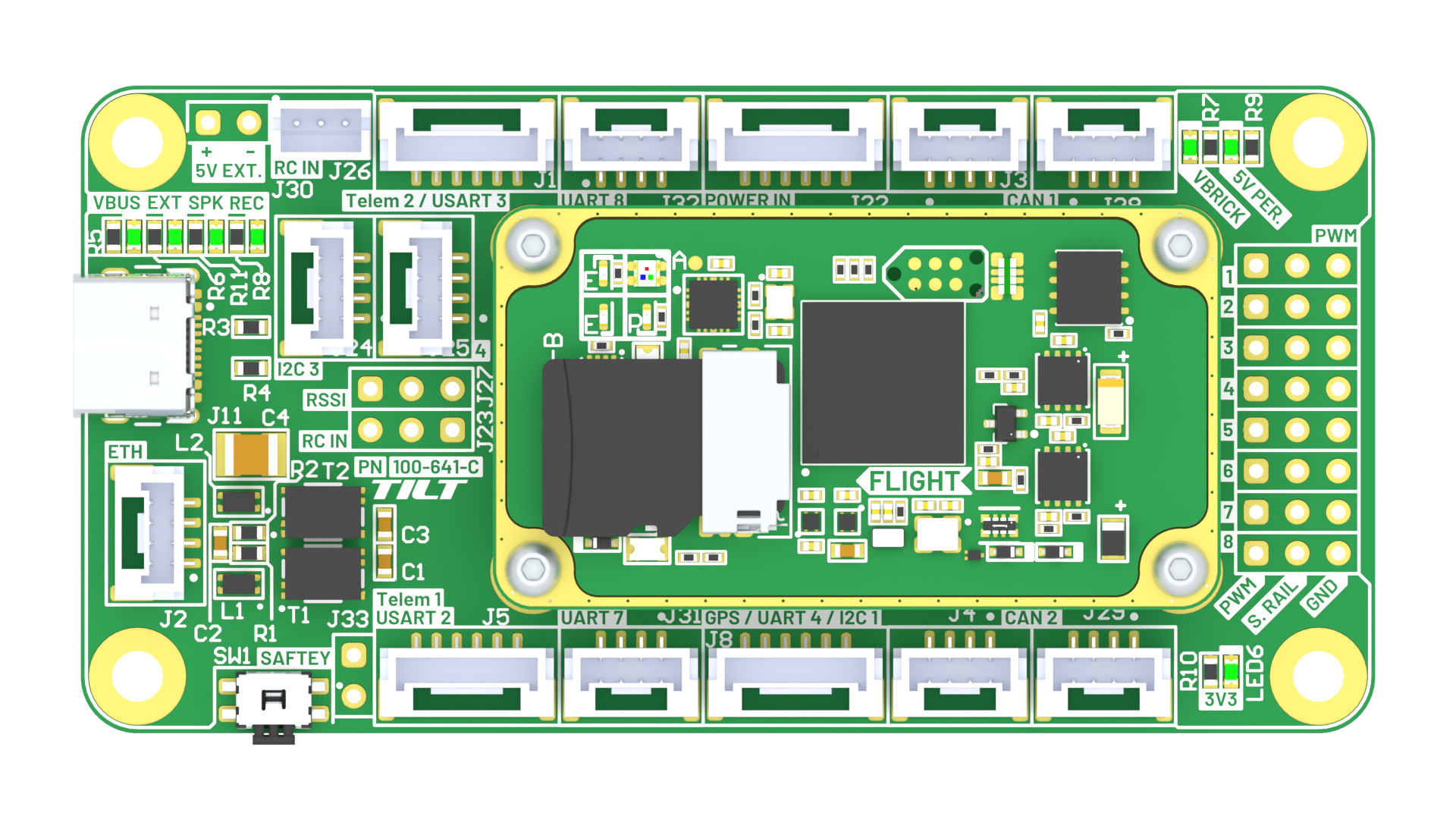
I/O Mapping
The TILT H7 carrier board provides comprehensive I/O connectivity for all communication interfaces, power, and control signals.
Flight System Port Diagram
Power Input
- Voltage: 5.0-5.1 VDC (strict tolerance - use regulated 5V supply)
- Current: ~300 mA typical (1.5W nominal)
Voltage Requirements
The TILT H7 requires a tightly regulated 5.0-5.1V power supply. Voltages outside this range may cause damage or unstable operation. Use a quality voltage regulator or BEC rated for the required current.
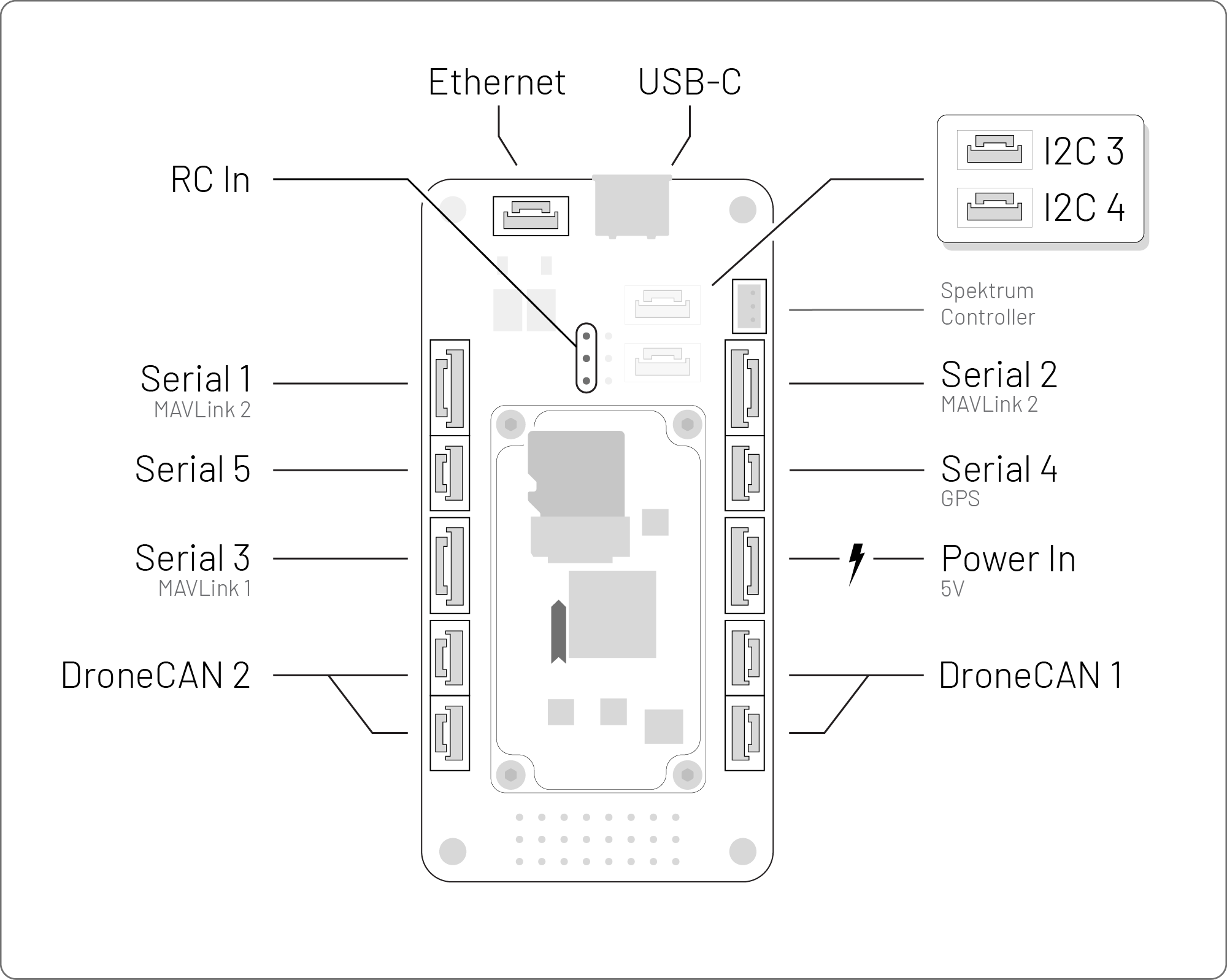
UART Ports (×5)
UART ports can be configured for GPS, telemetry radios, companion computers, or other serial peripherals.
Telemetry 1 (USART2)
Telemetry 2 (USART3)
GPS / UART4 / I2C1
UART7
UART8
CAN Ports (×2)
Dual CAN buses support DroneCAN/UAVCAN peripherals including GNSS receivers, smart batteries, ESCs, and sensors.
CAN1
CAN2
CAN Termination
Each CAN bus should have 120Ω termination resistors at both ends of the bus. External DroneCAN devices (like TILT GNSS) may have internal termination that can be enabled via parameters.
I2C Ports (×2)
I2C ports support external sensors, airspeed sensors, displays, and other I2C peripherals.
I2C3
I2C4
Ethernet Port
Native Ethernet connectivity enables high-bandwidth communication with companion computers, ground stations, or network devices.
Ethernet Capabilities
Ethernet support in ArduPilot enables MAVLink over UDP/TCP, parameter downloads, log retrieval, and integration with vision systems or AI compute modules.
USB-C Port
USB-C connection for firmware flashing, configuration, and MAVLink communication with ground control software.
RC Input Port (PPM Only)
The dedicated RC input connector uses a hardware timer optimized for PPMSum protocol only. For serial-based RC protocols (SBUS, CRSF, ELRS, etc.), use a UART port instead (see Serial-Based RC Input).
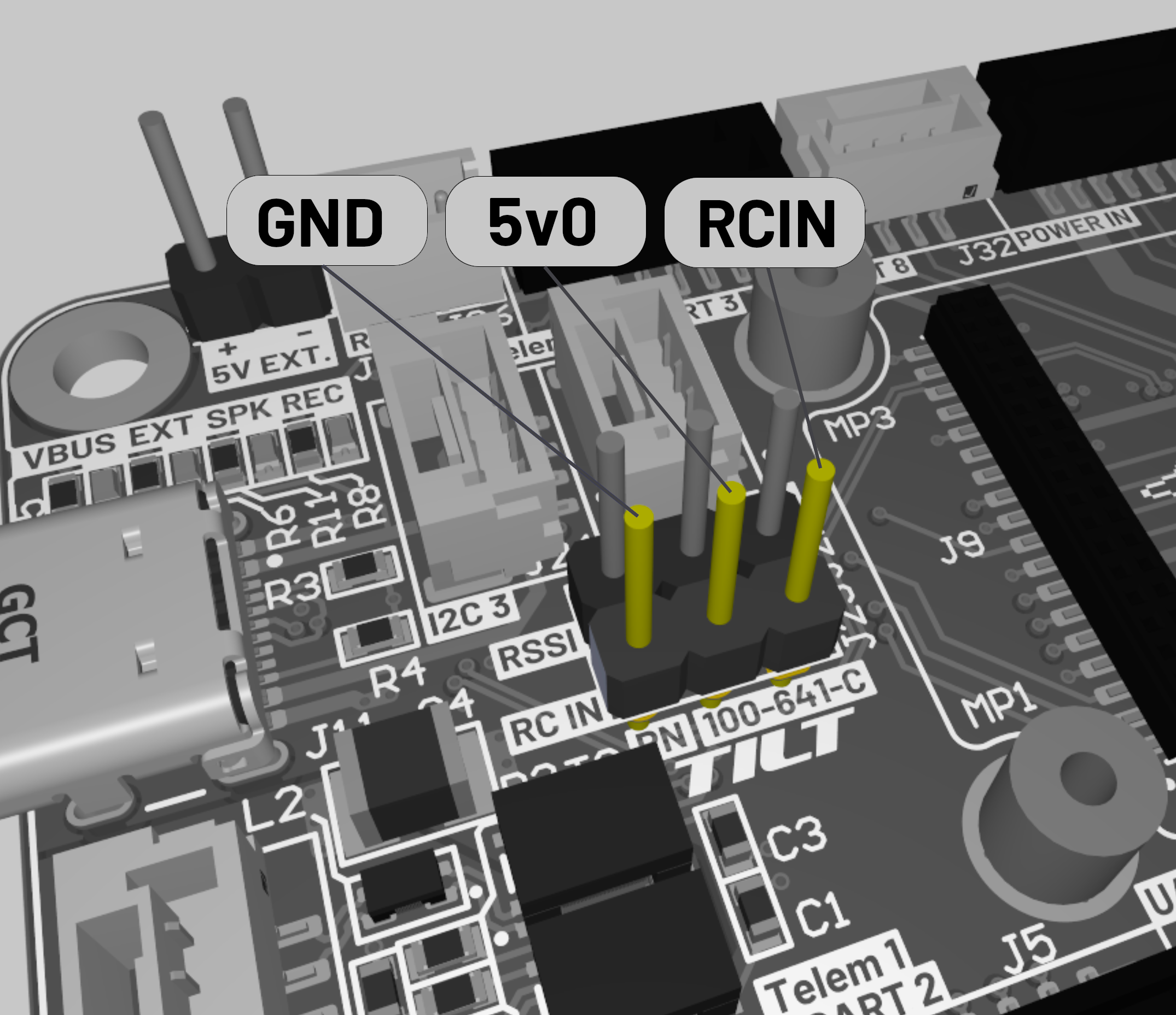
RC Input Connector Pinout (PPM Only)
Use UART for Serial Protocols
The RC_IN pin supports soft serial as a fallback, but this is not recommended due to potential reliability issues. Serial protocols (SBUS, CRSF, DSM, FPORT, IBUS, etc.) should always use a UART port with SERIALn_PROTOCOL = 23.
Spektrum Satellite Receivers
For Spektrum satellite receivers (DSM/DSM2/DSMX protocols), use the dedicated JST-ZH 2-pin Spektrum connector on the carrier board instead of the main RC input port.
PWM Channel Mapping
The TILT H7 provides 8 PWM output channels with flexible configuration for various vehicle types and actuator arrangements.
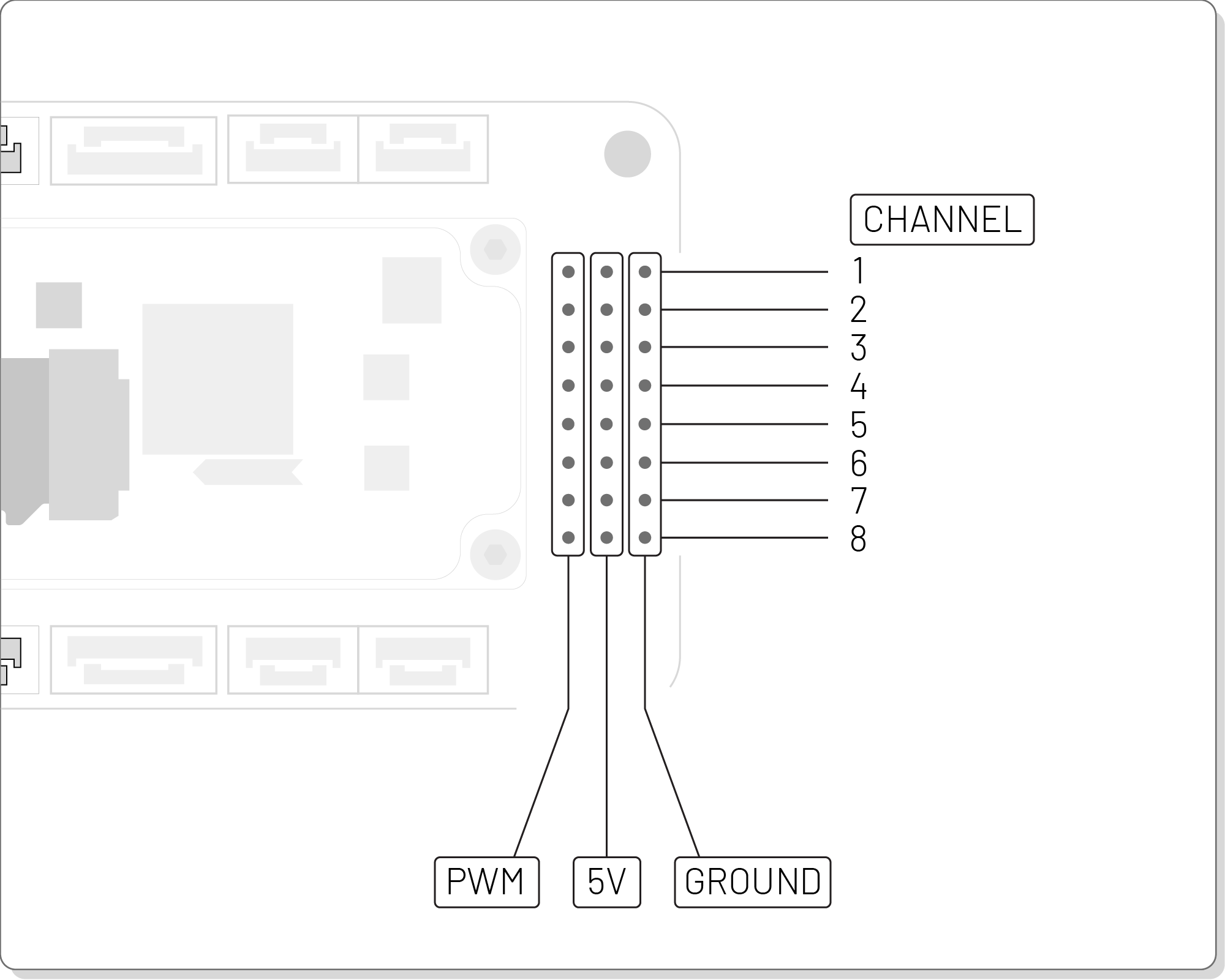
PWM Channel Assignments
Channel Configuration
PWM channels can be configured via ArduPilot parameters (SERVOx_FUNCTION) for motors, servos, relays, or GPIO. Consult ArduPilot documentation for detailed output configuration options.
Dimensions & Mounting
Dimensions: 80 mm × 40 mm × 9.5 mm (L × W × H) Weight: 18.4 g (with carrier board) Mounting: Standard 30.5 mm × 30.5 mm hole pattern (compatible with common flight controller mounting)
Dimension Diagrams Coming Soon
Detailed mechanical drawings with mounting hole locations and clearance dimensions will be added in a future update.
DroneCAN Integration
The TILT H7 supports DroneCAN/UAVCAN communication on both CAN ports, enabling a distributed sensor and actuator architecture with hot-swappable peripherals, automatic node discovery, and firmware updates over CAN.
The TILT H7 supports standard DroneCAN/UAVCAN messages per the official specification. For complete DroneCAN message definitions and protocol details, see:
- DroneCAN Specification: dronecan.github.io
- ArduPilot DroneCAN Documentation: ardupilot.org/dev/docs/dronecan
- TILT DroneCAN API Reference: DroneCAN API documentation
Installation Guide
Mounting Best Practices
- Orientation: Mount with the arrow marking pointing toward the vehicle's forward direction (use
AHRS_ORIENTATIONparameter if non-standard mounting is required) - CG Placement: Mount as close to the vehicle's center of gravity as possible to minimize rotational acceleration effects on IMU measurements
Proper Orientation Critical
The FMU must be mounted with the orientation arrow pointing forward. Incorrect orientation will result in incorrect attitude estimates and potential flight control issues. If non-standard mounting is required, set the AHRS_ORIENTATION parameter accordingly.
Vibration Management
The TILT H7's sensors are sensitive to high-frequency vibrations from motors and propellers. Poor vibration isolation can degrade IMU performance and flight stability. For high-vibration vehicles, use mechanical isolation and/or digital filtering.
Mechanical Isolation Methods: - Soft-mount using 3M double-sided foam tape or gel pads - Use commercial vibration damping mounts or O-ring suspension mounts - Keep motor/propeller vibrations below 300 Hz at the IMU - Balance propellers and motors for minimal vibration
Digital Filtering: - For persistent high-frequency vibration, configure ArduPilot's dynamic notch filters - See ArduPilot Notch Filter Documentation for setup and tuning
Verify vibration levels by checking ArduPilot's VIBE log message - accelerometer clipping should be <100 per axis.
Power Supply Requirements
Critical Power Requirements
Voltage: 5.0-5.1 VDC (strict tolerance) Current Capacity: Minimum 500 mA continuous (to handle peak loads) Regulation: ±50 mV max ripple Brownout Protection: Recommended below 4.8V
Use a high-quality switching regulator or linear regulator rated for the required current. Poor power quality can cause sensor errors, brownouts, or permanent damage.
ArduPilot Configuration
The TILT H7 ships with ArduPilot bootloader pre-installed. Follow standard ArduPilot setup procedures for your vehicle type.
Firmware Installation
Coming soon - Detailed firmware installation instructions will be added in a future update.
DroneCAN Setup
To use DroneCAN peripherals (GNSS, ESCs, smart batteries):
- Enable CAN drivers:
CAN_P1_DRIVER = 1(First CAN port)CAN_P2_DRIVER = 1(Second CAN port)- Set CAN bitrate:
CAN_P1_BITRATE = 1000000(1 Mbps recommended) - Enable DroneCAN protocol:
CAN_D1_PROTOCOL = 1(DroneCAN) - Reboot flight controller
- DroneCAN devices should auto-discover - check in ground control software
CAN Troubleshooting
If DroneCAN devices don't appear, verify: proper wiring (CAN_H, CAN_L, GND), 120Ω termination at both ends of bus, and that device node IDs don't conflict.
Ethernet Configuration
The TILT H7's native Ethernet port enables high-speed communication with companion computers or ground control stations.
Enabling Ethernet MAVLink
Configure a serial port for Ethernet UDP:
Use Cases
- Companion Computer Integration: High-bandwidth MAVLink to Raspberry Pi, Jetson, or other compute modules
- Ground Station: Direct Ethernet connection for parameter download, log retrieval
- Vision Systems: Low-latency streaming of position estimates from visual odometry or object detection
Ethernet Performance
Ethernet provides significantly higher bandwidth and lower latency compared to serial telemetry, making it ideal for vision-based navigation, high-rate sensor fusion, or real-time video streaming.
LED Indicators
The TILT H7 includes status LEDs following standard ArduPilot patterns:
Initialization States
| LED Pattern | Description |
|---|---|
| Flashing Red and Blue | Initializing gyroscopes (hold vehicle still and level) |
Disarmed States
| LED Pattern | Description |
|---|---|
| Flashing Blue | Disarmed, no GPS lock |
| Flashing Green | Disarmed, GPS lock acquired (ready to arm) |
| Fast Flashing Green | Disarmed, GPS using SBAS (high-quality position) |
| Double Flashing Yellow | Failing pre-arm checks (see GCS messages) |
Armed States
| LED Pattern | Description |
|---|---|
| Solid Blue | Armed, no GPS lock |
| Solid Green | Armed, GPS lock acquired (ready to fly) |
Failsafe/Error States
| LED Pattern | Description |
|---|---|
| Single Flashing Yellow | Radio failsafe activated |
| Flashing Yellow (rapid beep) | Battery failsafe activated |
| Flashing Yellow and Blue | GPS glitch or GPS failsafe |
| Flashing Red and Yellow | EKF or Inertial Nav failure |
Pre-arm Check Failures
Common pre-arm failures include: compass not calibrated, accelerometer not calibrated, GPS no fix, RC calibration required, or safety switch not pressed. Check ground control software messages for specific failure reasons.
For complete LED indicator reference, see ArduPilot LED Meanings Documentation.
Troubleshooting
Common Issues and Solutions
| Issue | Possible Cause | Solution |
|---|---|---|
| FMU not detected via USB | Driver issue or faulty cable | Install STM32 drivers, try different cable |
| Poor IMU performance | Excessive vibration | Improve vibration isolation, check VIBE logs |
| GPS not detected | Wrong SERIAL protocol | Set SERIAL1_PROTOCOL = 5 for GPS |
| DroneCAN devices not found | Wiring or termination issue | Verify CAN_H/CAN_L, check 120Ω termination |
| Brownouts or resets | Insufficient power supply | Use regulated 5V supply with ≥500 mA capacity |
| Compass errors | Magnetic interference | Increase distance from power cables/motors |
| RC input not responding | Wrong port or protocol | For serial protocols (SBUS, CRSF, DSM, etc.), use UART with SERIALn_PROTOCOL = 23; RC_IN pin is for PPM only |
Support & Ordering
For technical support or ordering information:
- Email: support@tiltautonomy.com
- Sales: solutions@tiltautonomy.com
Custom Integration Support
TILT Autonomy offers custom integration support, firmware customization, and system-level consulting for autonomous vehicle projects. Contact our solutions team for more information.