100-100-B: TILT GNSS
Overview
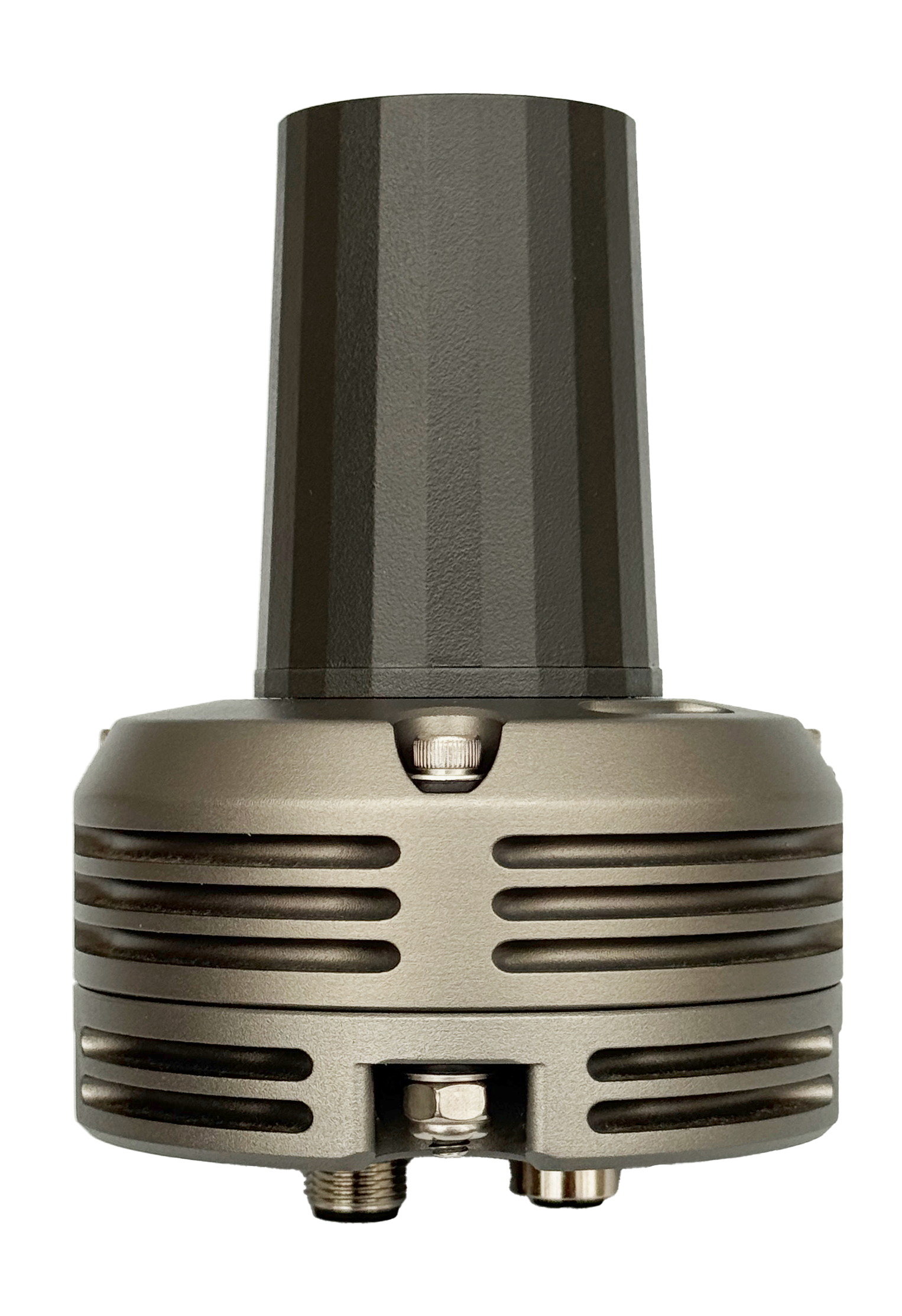
The TILT GNSS is a rugged, high-precision GPS/GNSS receiver designed for demanding autonomous vehicle applications. Engineered for reliability and accuracy, it provides RTK-capable positioning data through DroneCAN integration, enabling seamless connectivity with flight controllers and vehicle management systems.
Specifications
Physical
- Weight: 0.85 lbs (385 g)
- Housing: Anodized Aluminum
- Environmental Rating: IP67
Electrical
- Input Voltage: 10.0-30.0 VDC
- Nominal Power Draw: 1.7 W
- Interface: DroneCAN/UAVCAN
- Connector Type: M12 A-code
GNSS Performance
- Channels: 184
- Constellations: GPS, GLONASS, Galileo, BeiDou, QZSS, SBAS
- Update Rate: Up to 20 Hz (RTK mode)
- Accuracy (Standard): ~2.5 m CEP
- Accuracy (RTK): 0.01 m + 1 ppm CEP (centimeter-level)
- Time to First Fix: 24 seconds (cold start), 2 seconds (aided/hot start)
- RTK Convergence Time: <10 seconds
Antenna
- Frequency Range: 1.16-1.606 GHz (L1/L2/L5 + L-band)
- Polarization: Right Hand Circular
- LNA Gain: 35 dB typ.
- Current Draw: 21 mA typ.
- Weight: 42 g
- Environmental Rating: IP67
- VSWR: 1.5
- Axial Ratio: ≤0.5 dB
Environmental
- Operating Temperature: -40°C to +85°C
- Shock & Vibration: MIL-STD-810
- Corrosion Resistance: Marine-grade
- Sealing: Fully sealed enclosure
Dimensions & Mounting
All dimensions are in inches.

Diameter Dimensions (inches)
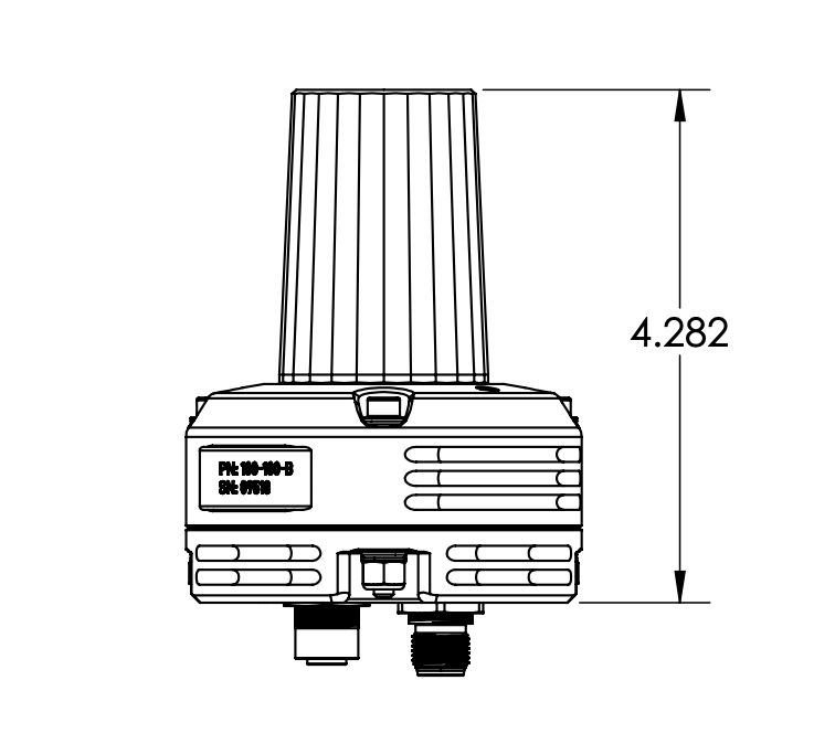
Height Dimensions (inches)
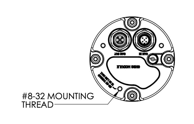
Mounting Pattern (inches)
3D Model
Explore the TILT GNSS adapter mounting design in 3D. Rotate, zoom, and pan to examine all details.
View in AR
Scan with mobile device
CAD Compatible:
SolidWorks, Fusion 360, FreeCAD, OnShape
Controls: Left mouse to rotate • Scroll to zoom • Right mouse to pan
Installation Guide
- To ensure waterproofing, mate all cables or plug unused ports with protective caps (Male: TE 2823064-1 | Female: Phoenix 1560251).
- Do not over-torque mounting bolts and over-compress isolation washers.
- Use of self-locking fasteners recommended for mounting.
- CAN Termination:
- 100-100-A: Internal 120Ω termination resistor is configured via DIP switch. Default is enabled.
- 100-100-B: Internal 120Ω termination resistor is configured digitally via the DroneCAN parameter
CAN_TERMINATE(set to 1 for enable, 0 to disable). Default is enabled. - External termination resistors can also be added where appropriate to terminate the lines for a total bus impedance of 60 ohms.
- Apply light amount of Loctite LB 8423 (or equivalent) dielectric grease to connector mating interfaces before connection. Wipe away excess after mating cables.
DroneCAN Integration
The TILT GNSS communicates via DroneCAN/UAVCAN protocol, providing real-time positioning data, velocity and heading information, satellite status and signal quality, fix type and accuracy estimates, and configuration and diagnostic messages.
DroneCAN Messages
The TILT GNSS communicates via DroneCAN/UAVCAN protocol with the following messages:
Messages Received by GNSS
RTK correction data for high-precision positioning
Messages Transmitted by GNSS
Primary GNSS fix data with position and velocity
HDOP, VDOP, and satellite information
Node health and armability status
GPS heading (dual antenna configuration)
RTK moving baseline data (base mode)
Relative position and heading information
Standard node health and status broadcasts
Connector Pinouts
The TILT GNSS uses industry-standard M12 A-coded 5-pin connectors for DroneCAN connectivity. Click images to enlarge.
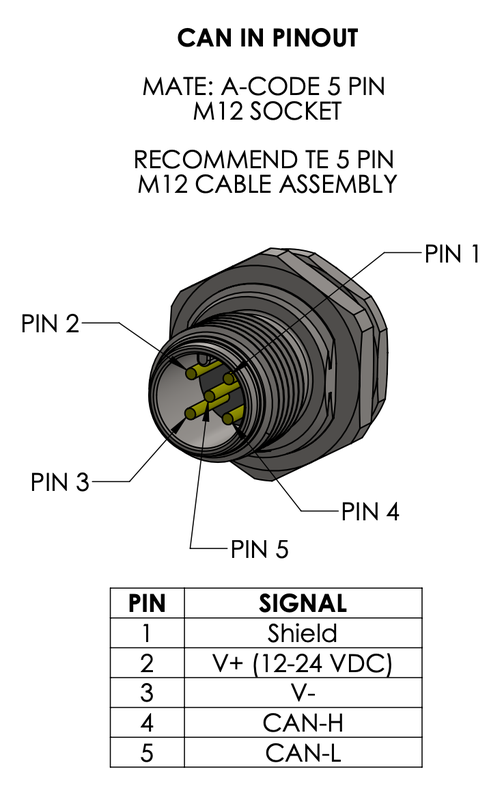
CAN In Port

CAN Out Port
M12 Connector Standard
Both CAN ports use M12 A-code 5-pin connectors compatible with standard industrial CAN bus cables. CAN_H, CAN_L, and GND are wired for daisy-chain topology.
RTK Corrections via NTRIP
The TILT GNSS supports Real-Time Kinematic (RTK) positioning for centimeter-level accuracy when RTK correction data is provided via DroneCAN.
How It Works
- Ground Control Station (GCS) or Flight Controller connects to an NTRIP caster to receive RTCM correction data from a base station
- Correction data is forwarded to the TILT GNSS via the
uavcan.equipment.gnss.RTCMStreamDroneCAN message - TILT GNSS processes the RTCM corrections and achieves RTK fix (indicated by blue LED)
- Positioning accuracy improves from meter-level to centimeter-level
ArduPilot Integration
When using ArduPilot as the flight controller:
- Configure NTRIP connection in ground control software
- Enter NTRIP caster details (server, port, mountpoint, credentials)
- ArduPilot automatically forwards RTCM data to DroneCAN GNSS receivers
- Monitor RTK status via GCS - the TILT GNSS will indicate blue LED when RTK fix is achieved
Supported RTCM Messages
The TILT GNSS supports standard RTCM 3.x messages including:
Stationary RTK reference station coordinates
GPS MSM7 (full carrier phase and code)
GLONASS MSM7
Galileo MSM7
BeiDou MSM7
GLONASS code-phase biases
RTK Base Station Requirements
For optimal RTK performance, the base station should be within 10-20 km of the rover. Accuracy degrades with distance due to atmospheric effects. Use a local NTRIP caster or set up your own base station for best results.
Moving Baseline (RTK Positioning Between Vehicles)
The TILT GNSS supports moving baseline mode, allowing two GNSS units to establish RTK positioning relative to each other without a fixed base station. This is ideal for multi-vehicle formations or leader-follower applications.
How Moving Baseline Works
- Base Unit configured as moving base station, broadcasts raw observation data via
ardupilot.gnss.MovingBaselineData - Rover Unit receives moving baseline data and computes relative position with centimeter-level accuracy
- Relative heading between units is transmitted via
ardupilot.gnss.RelPosHeading - Both units can be in motion - no stationary base required
Configuration Requirements
- Both GNSS units must support moving baseline (100-100-B hardware)
- ArduPilot firmware with moving baseline support
- DroneCAN communication between base and rover
- Configure one unit as base (GPS_TYPE = 22) and one as rover (GPS_TYPE2 = 23)
Moving Baseline vs. Traditional RTK
Moving baseline provides relative positioning between two units, while traditional RTK provides absolute position relative to a fixed base station. Both can achieve centimeter-level accuracy, but serve different use cases.
Antenna Placement Best Practices
Proper antenna placement is critical for achieving optimal GNSS performance:
Mounting Location
- Clear sky view - Minimum 30° above horizon in all directions
- Away from obstructions - No metal structures, carbon fiber, or electronics directly above antenna
- Elevated position - Mount on highest point of vehicle when possible
- Away from interference - Keep >15 cm away from motors, ESCs, power cables, and RF transmitters
Ground Plane Considerations
The integrated antenna does not require a ground plane, making it ideal for UAV applications. However, mounting on a metal surface can improve multipath rejection.
Multi-Antenna Setup (Dual GNSS for Heading)
When using two GNSS units for heading: - Keep antennas at least 30 cm apart - greater separation provides more accurate heading - Mount both antennas rigidly so they don't move relative to each other - Place them at the same height when possible - The primary antenna goes toward the front of the vehicle
Interference Sources
Avoid mounting near: 2.4 GHz WiFi/Bluetooth transmitters, 5.8 GHz video links, high-power RF transmitters, switching power supplies, or CPU/GPU modules. These can degrade GNSS signal quality and increase time to fix.
Magnetometer (Compass)
The TILT GNSS includes an integrated magnetometer for compass heading when GPS heading is unavailable or as a backup heading source.
Orientation Requirements

Orient unit with direction icon pointing toward vehicle's forward direction
Critical: The TILT GNSS must be mounted with the orientation icon on the top surface pointing toward the vehicle's forward direction. Incorrect orientation will result in heading errors and potential flight control issues.
3D Compass Calibration
A full 3D magnetometer calibration must be performed after installation and whenever the unit is remounted or the vehicle configuration changes.
Why 3D Calibration is Required: - Compensates for local magnetic distortions from vehicle structure and electronics - Accounts for hard-iron effects (permanent magnets, ferrous materials) - Corrects for soft-iron effects (induced magnetic fields) - Ensures accurate heading in all orientations
When to Calibrate: - After initial installation - After moving the GNSS unit to a different location on vehicle - After adding/removing equipment near the GNSS - When compass variance warnings appear - After any structural changes to the vehicle
Calibration Best Practices: - Perform calibration away from magnetic interference sources - Keep motors and ESCs powered off during calibration - Rotate vehicle slowly and smoothly through all axes - Ensure complete coverage of all orientations (pitch, roll, yaw) - Verify calibration quality metrics after completion
Magnetic Interference
Mount the TILT GNSS as far as possible from: motors, ESCs, power distribution boards, high-current cables, speakers, steel/iron components, and battery packs. Minimum recommended distance is 20 cm from high-current power cables.
Compass Priority
When GPS heading is available (dual GNSS setup or moving at sufficient speed), it provides more accurate heading than the magnetometer. Configure your flight controller to prioritize GPS heading over compass heading when available.
Configuration
The TILT GNSS can be configured via DroneCAN parameters:
| Parameter | Description | Default | Range | Applies To |
|---|---|---|---|---|
CAN_TERMINATE |
Enable internal 120Ω termination resistor | 1 (enabled) | 0-1 | 100-100-B only |
GNSS_NODE_ID |
DroneCAN node ID | TBD | 1-125 | All versions |
GNSS_UPDATE_RATE |
Position update rate (Hz) | TBD | TBD | All versions |
Parameter Access
Parameters can be accessed using DroneCAN GUI tool or other compatible ground control software.
LED Indicators
White
Powered up, initializing
Green
Standard GNSS fix acquired
Blue
RTK fix achieved (high-precision)
Disabling LEDs
LEDs can be disabled for stealth operations by setting the DroneCAN parameter NTF_LED_BRIGHT to 0. This completely turns off all status LEDs while maintaining full GNSS functionality.
Troubleshooting
Common Issues and Solutions
| Issue | Possible Cause | Solution |
|---|---|---|
| No GNSS fix | Obstructed antenna view | Ensure clear sky view, relocate if needed |
| Low accuracy | Insufficient satellites | Wait for more satellites, check antenna |
| No DroneCAN communication | Wiring or termination issue | Verify pinouts, check termination resistors |
Support & Ordering
For technical support or ordering information:
- Email: support@tiltautonomy.com
- Sales: solutions@tiltautonomy.com
- Warranty: 1-year limited warranty against manufacturing defects (excludes damage from improper installation, misuse, or operation outside specifications)